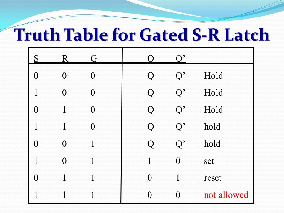
Gated S R Latch Truth Table
Gated S R Latch Instrumentationtools
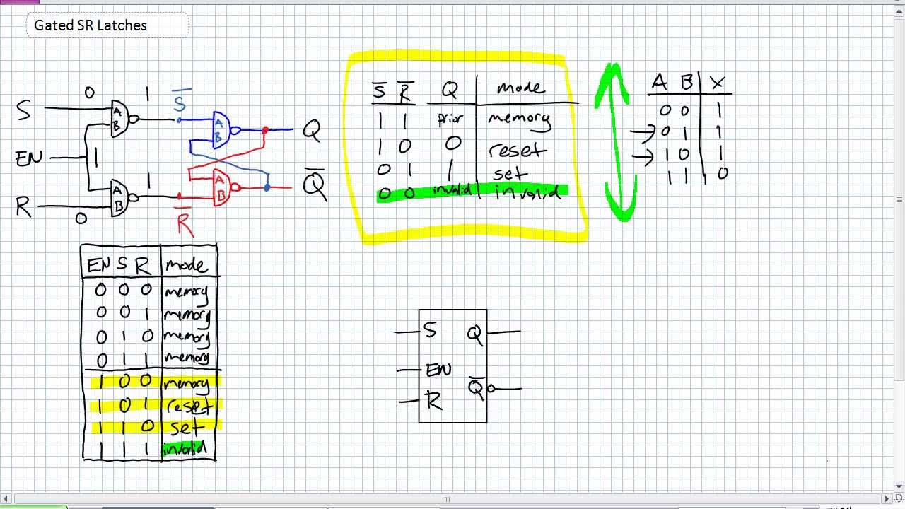
Gated Sr Latches Youtube

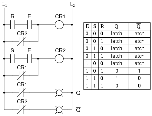
The Gated S R Latch Creating Gated Sr Latch How It Works Truth Table The Identical Function In Ladder Logic Of Gated S R Latch Multivibrators Elektropage Com
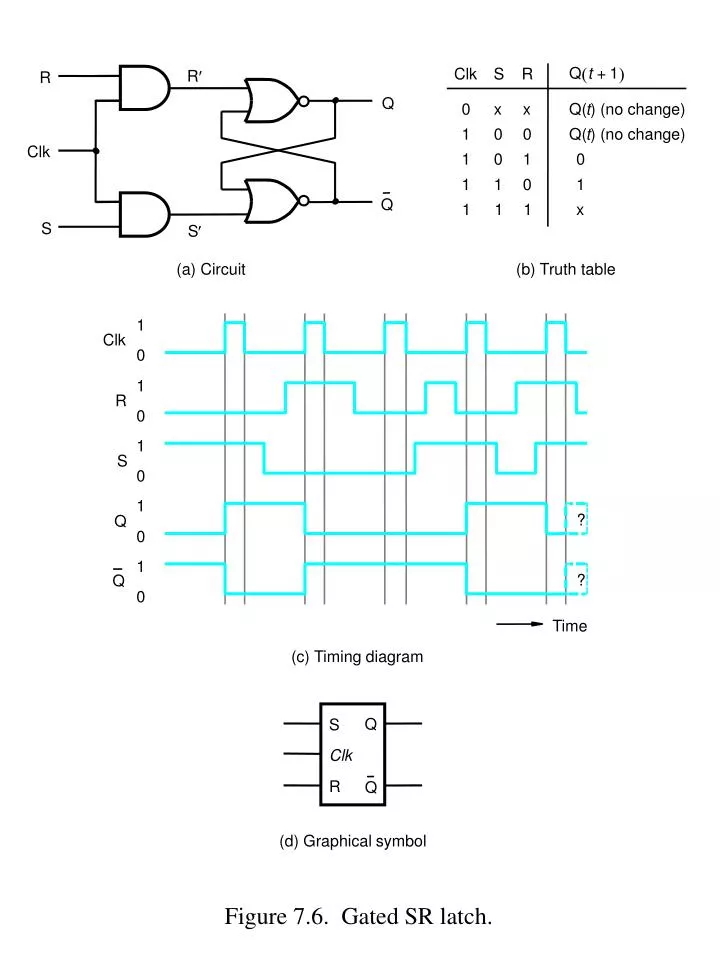
Ppt Figure 7 6 Gated Sr Latch Powerpoint Presentation Free Download Id 4122222
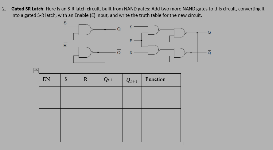
Solved Gated Sr Latch Here Is An S R Latch Circuit Buil Chegg Com
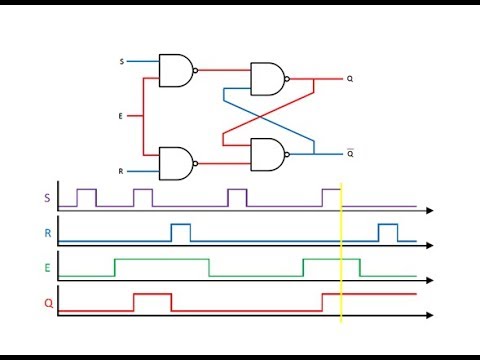
Latches And Flip Flops 2 The Gated Sr Latch Youtube
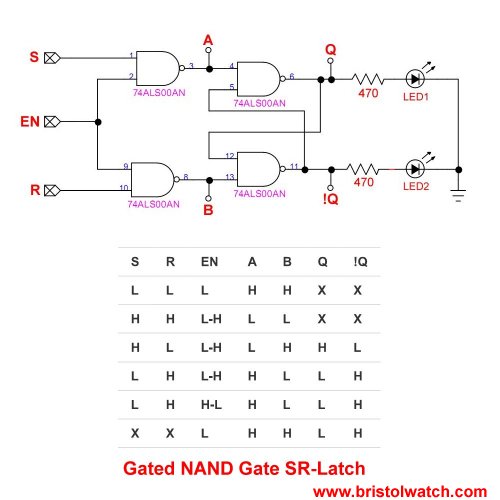
2 sr latch using nand gate.
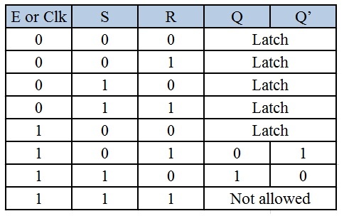
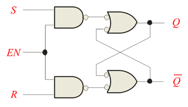
Gated s r latch truth table. When s 0 and r 1 then by using the property of nand gate if one of the inputs to the gate is 0 then the output is 1 therefore q becomes 1 as s 0 putting the latch in the set state and now since q 1 and r 1 then q becomes 0 hence q and q are complement to each other. Sr flip flop can also be designed by cross coupling of two nor gates. The input nand stage converts the two d input states 0 and 1 to these two input combinations for the next sr latch by inverting the data input signal. The sr latch truth table and working of the sr latch are given below.
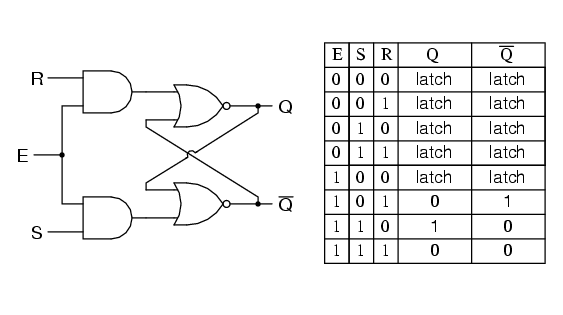
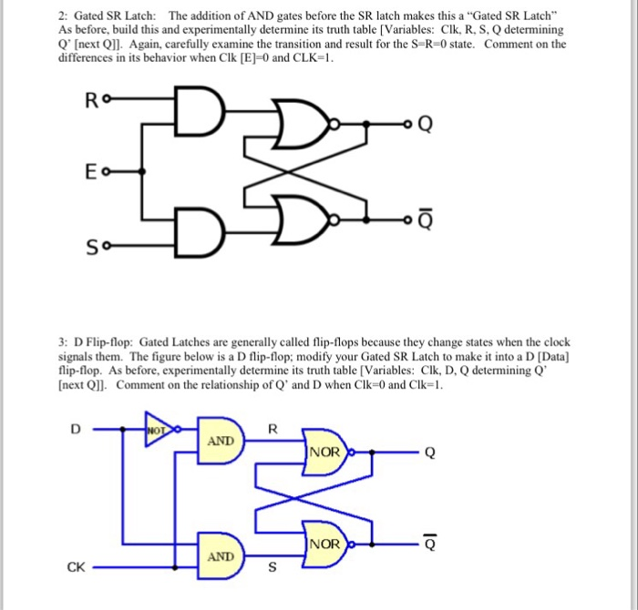
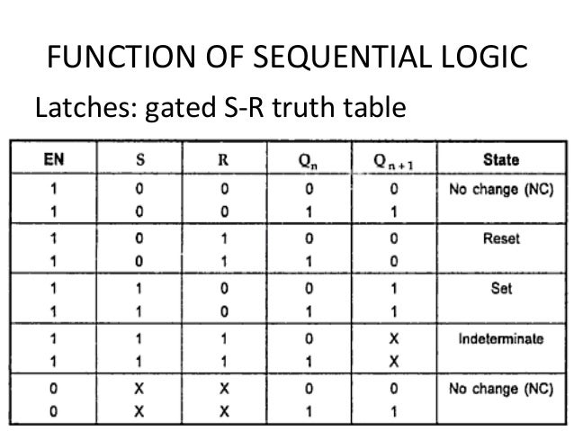
Gated sr latch truth table when the e 0 the outputs of the two and gates are forced to 0 regardless of the states of either s or r. As the outputs of sequential circuits depend on present and previous states these are represented in the form of table called state table and it shows the next state based on the present state and other inputs. Because from the nand truth table even one low input gives you a high output. The characteristic table for a gated sr latch which describes its behavior is as follows.
The s r latch using nand gate is active low. You can learn more about clocked sr flip flops and other logic gates by checking out our full list of logic gates questions. Case 1 for the input s 1. Add two more nand gates to this circuit converting it into a gated s r latch with an enable e input and write the truth table for the new circuit.
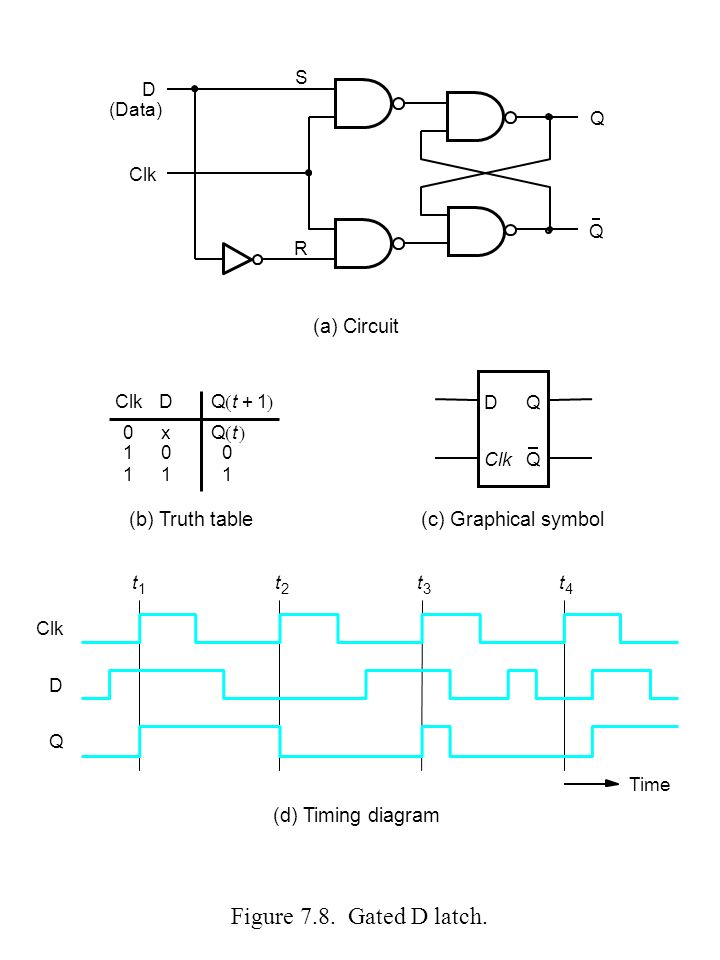
Clk s r q comments 0 q no change typically stable statesq 0 q 1orq 1 q 0 1 0 0 q no change typically stable statesq 0 q 1orq 1 q 0 1 0 1 0 reset 1 1 0 1 set. This latch exploits the fact that in the two active input combinations 01 and 10 of a gated sr latch r is the complement of s. Only when the enable input is activated 1 will the latch respond to the s and r inputs. Now when the s input goes back to 1 the circuit.
State transition table or truth table of sr latch state table is similar to truth table in combinational circuits that gives the information about the states of a circuit. Here is an s r latch circuit built from nand gates. The truth table for a gated sr latch or gated sr flip flop has been shown in the table below. There are also d latches jk flip flops active low sr flip flops and gated sr flip flops.
Consequently the circuit behaves as though s and r were both 0 latching the q and not q outputs in their last states. Working of sr nand latch. The circuit of sr flip flop using nor gates is shown in. Unclocked s r flip flop using nor gate.
It is an active high input sr flip flop. The table below summarizes above explained working of sr flip flop designed with the help of a nand gates or forbidden state. R 0 the output of the lower nand gate is 1.
Solved I Need To Combine These Three Diagrams As On Circu Chegg Com
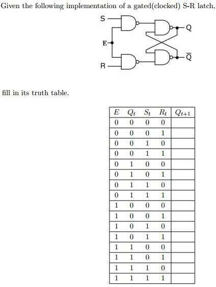
Solved Given The Following Implementation Of A Gated Cloc Chegg Com
Introduction To Latches
Digital E Chap 4
Gated S R Flip Flop

Tutorial Nor Gate Sr Latch Circuit

Instructor Alexander Stoytchev Ppt Download

Telecommunication And Electronics Projects Gated Sr Latch Using Nor Gates
10 3 The Gated S R Latch
What Is The Difference Between An Sr Latch And An Sr Ff What About A D Latch And A D Ff Quora
Ekt 124 3 Digital Elektronic 1 Ppt Video Online Download
Basic Nand Gate Sr Latch Circuit

Eet 1131 Unit 10 Flip Flops And Registers Ppt Video Online Download